Wednesday, August 25, 2010

Hubs

The hub is the middle part of the wheel, to which the inside ends of the spokes attach. Consists of an axle which attaches to the fork ends; a shell, to which the spokes attach, and bearings to connect the axle to the shell, permitting the shell to revolve around the axle. In the case of a rear hub, the shell would also have a provision for attaching the rear sprockets.

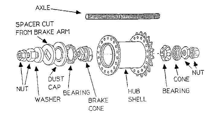
There are two general types of hubs:
  1. Adjustable cup-and-cone: has loose ball bearings that can be adjusted for bearing play
  2. Cartridge: the bearings, races, and cones are all assembled as a complete cartridge unit.

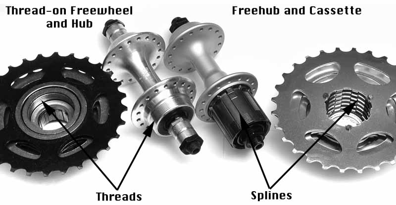
The freewheel is the mechanism that makes coasting possible. A ratchet mechanism allows the rear sprockets to drive the wheel forward but also allows the wheel to turn forward independently even when the sprockets are not turning. Freewheels are commonly sold with the sprockets attached, so this term is frequently used as a synonym for a cluster. A standard freewheel attaches to a hub by screwing on external threads that are part of the hub. The action of pedaling tightens the freewheel down to the threads, so no tools are required for installation. Removing a freewheel requires a special tool known as a "freewheel puller/extractor".
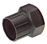
The freewheel puller/extractor is a splined unit that may be mounted on a vise or turned with a wrench. The splines engage matching splines in the interior (non-rotating) part of the freewheel body. Different brands of freewheels have used different spline patterns, but there is a recent tendency to standard on the Shimano pattern.
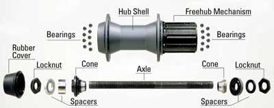
The freehub is the Shimano trademark for a rear hub in which the freewheel mechanism is built into the hub itself, rather than being part of the sprocket cluster.

A cluster is a group of rear sprockets on a multi-speed bicycle. If the bicycle uses a thread-on freewheel, the term "cluster" would include the entire assembly including the freewheel mechanism. In the case of a cassette hub, the "cluster" would only consist of the sprockets and the spaces that separate them.

A cassette is a cluster of sprockets and spacers designed for use on a freehub. Some of the sprockets and spacers may be semi-permanently attached on one another by bolts or rivets.

What is the main difference between freewheels and cassette freehubs?

Traditional rear hubs come with a standardized set of threads to which a standard freewheel/sprocket cluster can be screwed onto. This allowed any brand of freewheel to be mounted on any brand of hub. If you wore out your sprockets, or wanted different gear ratios, you could unscrew the cluster and install a new one. Almost all bikes through the late '80s used this system.

Over the last few years, the Shimano freehub has largely replaced the conventional threaded rear hub. These hubs work better but you can no longer interchange hubs.

Why do you need to overhaul your hubs?

To maintain performance levels. Once dirt enters the bearing system, it acts like sand paper grinding down all the moving parts.

Tools to overhaul an adjustable hub:
  1. Rags
  2. Grease
  3. 17mm open end wrench
  4. 13mm cone wrench for the front hub
  5. 15mm cone wrench for the rear hub
How to disassemble and service an adjustable FRONT hub
  1. Remove the quick release skewer
  2. Place the wheel on its side and slide a cone wrench onto the cone flats and then loosen the locknut with the 17mm open end wrench by turning it counter-clockwise against the cone wrench
  3. Completely unthread and remove the cone, locknut and any washers
  4. Put your hand over the end of the hub from which you removed the nuts and spacers (to catch bearings) and flip the wheel over. Have a rag underneath to catch stray bearings.
  5. Slide the axle out fro the right side of the hub. Unless your axle is bent and needs replacing, leave the cone and locknut in place. If you do need to replace it, measure the amount of axle sticking out beyond the locknut.
  6. With a screwdriver, gently pop off the seals that are pressed into either end of the hub shell. Be careful not to deform them; leave them on if you can't pop them out without damage.
  7. Clean off all of the old grease off of the axle and cones and remove all of the bearings from both sides, making sure to count how many you take out.
  8. Clean the insides of the hubs thoroughly and carefully inspect both the cones and the inner bearing races. Use a ballpoint pen to trace the bearing path. Roughness and wear twill be felt as the small ball of the pen passes over pits. If there is any damage such as pitting then the cone and/or hub should be replaced.
  9. If you don't replace the ball bearings, make sure to clean them thoroughly by rubbing all of them between two rags. A lack of sheen on either balls or cones indicates wear and is cause for replacement.
How to reassemble an adjustable hub
  1. Press the dust covers in both ends of the hub shell
  2. Grease heavily inside the hub shell cup. Sheldon Brown says it's impossible to use too much.
  3. Carefully insert all of the new bearings by pushing them down into the grease. When all of the bearings are installed, there should be at least half a bearing space left. Cover all bearings with a layer of grease.
  4. Lightly grease the axle threads and the cone that is still attached to the axle and then slide the axle into the hub shell. Lift the wheel up a bit (30 degree angle) so that you can push the axle in until the cone slides into position and keeps all the bearings in place.
  5. Holding the axle pushed inward with one hand to secure the bearings, turn the wheel over.
  6. Smear grease into the bearing race that is now facing up. Lift the wheel and allow the axle to slide down just enough so that it is not sticking up past the bearing race. Make sure no bearings fall out of the bottom.
  7. While the top end of the axle is still below the bearing race, place the remaining bearings uniformly around the grease.
  8. Slide the axle hub back into place by setting the wheel down on the table, so that the cone is seated up into the bearings.
  9. With your fingers, screw the top cone into place, seating it snugly onto the bearings. Covering the top cone with a film of grease is also a good idea.
  10. In the correct order, slide on the washer and any spacers. Watch for those washers with a little tooth or "key" that fits the lengthwise groove in the axle.
  11. Use your fingers to screw on the lock nut. Note that the two sides of the locknut are not the same.
Adjusting the bearings determines how far apart the cones are from one another on the axle. If they're too close together they will pinch and bind against the balls and the axle will be difficult to turn. This means that the bearings would have too much friction and the parts will wear out prematurely. If the cones are too far apart, everything may roll freely enough, but there will be looseness or play in the bearings and your wheel will wobble side to side like a loose tooth. The ideal is to find the point where the cones are loose enough that the axle turns as freely as it does when the cones are too loose, but with as little play as possible.

You

Clincher Tires


Bike Tire Sizes
  • Diameter (the A part of A x B)
    • The size of a tire can be found on the sidewall. This measurement is written as two numbers, separated by an X. For ex: 700 x 23 or 26 x 2.10. The first number is the diameter of the bead of the tire, in mm or in. Most adult bikes come in either the 700mm size or the 26in size. You'll find 700 tires on road bikes and 26 tires on mountain bikes.
  • Width (the B part of A x B)
    • The second number on the tire's sidewall. On a 700 x 23 tire, the width of the tire is 23mm. As the width increases, the tire will have more surface contact with the ground. More surface contact gives you a more stable and comfortable ride. Less, however, means less friction and a faster ride.
  • Width Fractions and Decimals
    • If you ride a bike with a 26in tire, the tire width will be denoted with either a decimal or a fraction--for ex: 26 x 1/75 or 26 x 1 3/4. Take note that even though the two tires appear to have the same width, if one is marked with a decimal and the other a fraction, they are actually two different sizes. If you're looking for an exact size match, make sure you don't choose one fraction tire and one decimal tire.
  • Measurement Discrepancies and the ISO
    • If you measure the diameter and width of your tire, you'll find that they don't exactly match what's written on the tire. The numerous sizing systems -- and companies that try to cheat on their sizes -- make it hard to know what the numbers on a tire really mean. Fortunately, the International Organization for Standardization, or ISO, has created a system for tire sizing to regulate tire measurement and take the guesswork out of choosing the proper tire. Most new tires and rims will show the ISO measurement. The measurement marks width first, followed by diameter. If you want an exact match when you replace an old tire, match the ISO number.
  • Compatibility
    • When it's time to buy new tires, always get tires with the same diameter as your old ones but you can choose a different width. Your bike's rims will hold a range of tire widths, although not all widths are recommended for every tire. See a tire width chart that shows proper compatibility.
Four most common tire sizes (for adult bikes):

Each group is roughly defined by the diameter of the tire with varying widths available within the same diameter.
  1. 700C: the most common tire size. Found on most road and hybrid bikes. Widths range from 20-23mm for fast road bikes and from 38-42mm for hybrids/touring bikes. It has an inner diameter measure (a.k.a. "bead seat diameter" [BSD]) of 622mm. A tire labeled 25-622mm == 700 x 25. There is, however, a huge variation of the "true" outer diameter among 700C tires. For ex: a 700 x 20 road bike tire may be as small as about 660mm in diameter. There is no foolproof way to know if it'll fit your wheel other than trial and error.
  2. 27 inch: 2nd most common tire size. Very popular on 10-speeds common from the '60s to '80s, but not many (or none) bikes are being made today based on this tire size. However, replacement 27-inch wheels are still available for these bikes, and the tires will probably continue to be produced for years to come. Though 27-inch and 700C tires use the same inner tubes, the tires themselves are not the same and should not be used interchangeably.
  3. 26 inch: prevalent on mountain and comfort bikes. Became the de facto standard of the mountain bike since the '70s. Commonly available in widths from 1.25 inches up to 2.5 inches. Standard BSD is 559mm. As with 700C tires, the true outer diameter of the 26 inch will vary from one brand and model of tires to the next.
  4. 650C: used on some triathlon/time trial bikes and smaller-framed women-specific bikes. Typically 1 inch in width. Not the same as 26-inch tires. 650C uses a BSD of 571mm. Similar to 700C and 27-inch, however, 650C and 26-inch inner tubes are interchangeable, given a close enough width.

Types of Bicycle Tires
  1. Road
    • smooth and narrow; no tread
    • typical size: 700 x 23c
    • heavier riders can ride up to 25-28mm widths
    • racers will use a narrower (18-20mm) width
  2. Hybrid
    • similar to road tires, but usually wider
    • typically at least 28mm and wider
    • may have tread pattern, but more for wet-weather street riding than for off-road
  3. Mountain
    • comes in a variety of width and tread patterns
    • width and tread are best determined by terrain
    • be sure to check rim width and frame and brake clearance when buying new MTB tires
29 (MTB) = 28 (Vintage) = 700C (modern designation) = 622 ISO. And 27 is bigger than them all at 630.

How to pick the right replacement tube
  1. Identify the valve type (Presta vs. Schraeder)
  2. Find the tire size written on the tire sidewall and find the closest tube match
  3. Diameter: It is always best to buy a tube that matches your tire in diameter. A 24" tube for a 24" tire, but close metric equivalent will also do the job as long as it's not too big of a difference
  4. Width: It's not as important to purchase the exact width of tire as the typical tube has a fair amount of elasticity to conform to your existing bicycle tire. However, it is the best approach to get in the habit of purchasing tubes that closely match your tire size. If you buy a slightly wider tube, say 1/2" more, it will not cause any harm or remain under-inflated, however it will be much heavier with the extra rubber. If you h

Wheels

A bicycle wheel consists of a hub, rim and spokes.

The hub is the middle part of the wheel, to which the inside ends of the spokes attach. It consists of an axle which attaches to the fork ends; a shell, to which the spokes attach; and bearings to connect the axle to the shell, permitting the shell to revolve around the axle. In the case of the rear hub, the shell would also have a provision for attaching the rear sprockets.


The clincher tire is used on 99% of all bikes and consists of an outer tire with a U-shaped cross section and a separate inner tube (basically a doughnut shaped rubber balloon) with air pressure keeping everything in place. The outer tire is made up of 3 parts:
  1. The beads: two hoops of strong wire that make up the edge of the tire and holds the tire to the rim
  2. The fabric cords forming the body of the tire, woven between the two beads.
  3. The rubber that covers all the other parts is mainly there to protect the fabric and has no structural importance. The thicker rubber that contacts the road is called the tread.


Wheel truing is the process to make a wheel spin straight and round by evening out the tension in the spokes. The typical bike wheel is composed of a rim suspended with tensioned spokes around a center hub. Each spoke pulls on a section of rim. Spokes coming from the right side hub flange pulls the rim to the right and vice versa. Spoke attached at the rim are then offset in a left-right-left-right pattern to counter the pull of the other side.

How is spoke tension adjusted?

By tightening or loosening a threaded nut, called the nipple, at the end of the spoke. Spoke nipples come in different sizes so the correct wrench must be used. The correct wrench is the smallest size that can be used. Make sure that the wrench is fully engaged before turning.

Are you tightening the spoke or the nipple?

You are ALWAYS rotating the nipple. Therefore, when you true a wheel and you view the wrench and nipple upside down, you will tighten by turning the wrench left. Just imagine a screwdriver at the nipple end and turn clockwise/counter-clockwise as needed.

Steps for Lateral Truing
  1. Carefully inspect the wheel for broken/bent spokes
  2. Grab the rim and flex it side to side to check for play in the hub bearings. If the bearings are loose, the wheel will clunk side to side. The hub will need to be tightened before you true the wheel, or else the wheel will behave erratically
  3. Mount the wheel in the truing stand, with the right side of the wheel on the right side of the stand
  4. Where the rim scrapes, loosen the spoke(s) closest to it and tighten the spoke(s) on the opposing end. This approach will pull the rim away from the caliper. When correcting a wheel that is laterally out of true, always adjust spokes in pairs: one spoke coming from one side of the wheel, the other from the opposite side.
  5. Check the wobble first on one side of the wheel and then the other, adjusting spokes accordingly, so that you don't end up pulling the wheel off-center by chasing wobbles only on one side. As the wheel gets closer to true, you will need to decrease the amount you turn the spokes to avoid overcorrecting.
How to stress-relieve spokes
  • You should always pre-stress the spokes and re-adjust before riding. Failure to do so can cause broken spokes later. There are two ways to do this:
    1. Squeeze together parallel spokes on both sides of the rim OR
    2. Rest the wheel sideways on the floor and gently push down on both sides of the rim, all the way around the wheel in 1/8 increments
  • After pre-stressing the spokes you will have to re-check and make some minor adjustments. If the rim looks severely warped afterwards, it means your spoke tension was too high. Loosen all spokes 1/2 turn and re-true the wheel.

Front Derailleur


The front derailleur consists of a cage that can move back and forth and from side to side. As it does so, it moves the chain between chainrings. It is attached to the frame, usually by a clamp surrounding the seat tube. There are different types of front derailleurs, the most notable differences include the type of mount and the direction that the cable pulls.

**Note: When using the barrel adjuster to change cable tension: counter-clockwise = increases the wire tension = towards bigger sprockets; clockwise = decreases wire tension = smaller sprockets.

The four front derailleur adjustments:
  1. Height
    • Height is the principle factor in how well it will shift. Best performance results from the very lowest position that still barely keeps the cage from hitting the chainring teeth. A 2mm clearance between the bottom of the outer cage plate and the teeth of the large chainring is often recommended.
    1. Shift to the outermost chainring and rear sprocket
    2. Common front derailleurs need a 5mm allen key or 8mm box wrench to loosen the band-clamp bolt
    3. The outer cage plate must be positioned over the largest chainring when viewing height
    4. Tighten the clamp so that it is secure, but loose enough to move around with your hand
    5. Position the bottom of the derailleur cage as close to the largest sprocket teeth as possible so that it still clears. Move on to setting the angle.
  2. Angle
    • This is set by looking down at the cage from above. This can be tricky and require some patience, as the shape of the derailleur cage is often not straight. You must position the outer plate of the derailleur cage parallel to the chainring so that the chainring sits equidistant and parallel to the cage plates.
    1. After following the above instructions for height, sight the chain from directly above to see if the outer cage plate and chainwheel are parallel.
    2. Rotate as needed and secure the bolt when you're done
  3. Limit Stops
    • The L-screw controls inward-most travel and the H-screw controls outward-most travel; just like the rear derailleur. On older derailleurs, the low-gear limit screw is closest to the frame, but some newer models have reversed the screw's positioning.
  4. Indexing Adjustments
    • Not all front derailleurs have an index setting. If the front shift lever is friction, there is no index setting.
    1. Shift to middle chainring and innermost rear sprocket
    2. View gap between inner cage plate and chain. Gap should be as small as possible without rubbing the chain.
    3. To reduce gap, increase wire tension by turning barrel adjuster counter-clockwise.
    4. If the chain is rubbing the cage, increase gap by lessening wire tension by turning barrel adjuster clockwise.
    5. If the adjuster is all the way in or out and no adjustment is possible, reset inner wire tension. Shift to innermost chainring and loosen inner wire pinch bolt. Turn in the barrel adjuster almost all the way clockwise. Pull wire gently with third-hand tool and tighten pinch bolt. Repeat steps 1 - 4.
    6. Test shift to all 3 chainrings.

Monday, August 23, 2010

Cables and Housing

Cables are used to control the gear shifting and brakes. They transmit force by a combination of tension on the inner cable and compression to the housing. Housing is the outer sleeve through which a brake or gear cable is pulled. The housing transmits an equal push to counter the pull on the inner cable.

BRAKE CABLES
Brake cables should be tight enough so that the lever cannot be pulled all the way to the grip, yet loose enough that the brakes are not dragging on the rims.

To increase cable tension (so the levers don't hit the grip) you must turn counter-clockwise. If you need to tighten the cable more than you can by simply fiddling with the barrel adjuster, first screw the barrel adjuster in clockwise most of the way to leave some adjustment in the system. Loosen the bolt clamping the cable at the brake and check the cable for wear. If you don't need to replace it, pull the cable tight and retighten the clamping bolt. Tension the cable as needed with the barrel adjuster.

To reduce cable tension (so the levers aren't so stiff/brakes don't drag) you must turn clockwise.
Make sure that the cable is tight enough so that the lever cannot be squeezed all the way to the grip.

How to lubricate brake cables
  1. Release the brake cable
  2. Compress the lever, pull on the housing and slide it through the barrel adjuster until the inner wire is exposed
  3. Carefully squeeze a few drops of oil into the inner cable just above where it runs down into the housing
  4. Slide the cable housing back into the barrel adjuster and re-connect the brake
Cable Installation
  1. Remove the old cable, making sure not to lose any parts of the cable clamps or straddle-cable holders
  2. Cut the housing sections long enough to reach the brakes and route them so they do not make any sharp bends. If you are replacing existing housing, look at where they bend before removing them. If the bends are smooth and do not bind when the wheel is turned or the suspension moves, cut the new housings to the same lengths
  3. After cutting, make sure that the ends are clean. If not, shear off extra bits or file it down until it's a flat circle.
  4. If the housing liner is mashed shut after cutting, open it up with a sharp object.
  5. Slip a ferrule over each housing end for support
  6. Tighten the adjusting barrel with one turn of being screwed all of the way in. Rotate the barrel adjuster and locknut so that their slots line up with those on the lever and lever body
  7. Insert the round head of the cable into the lever's cable hook
  8. Pull the cable down into the lined-up slots on the barrel and nut. Once the cable is in place, turn the barrel so that the slots are offset to prevent the cable from slipping back out
  9. REAR: Slide the rear-wheel brake cable through the housing sections and then route the cable and housing from the brake lever to the brake, snapping the housing and cable into the slot in each stop
  10. FRONT: With a V-brake, terminate the housing in the top of the "noodle" guide tube. On a cable-actuated disc brake, the housing usually terminates at a stop on the brake caliper. With a cantilever brake and a suspension fork, terminate the front-brake housing at the stop on the fork brace. For cantilevers without suspension, you may have a cable stop that is integral to the stem or one attached to the headset.
  11. Attach the cable to the brake. Pull the cable taut and tighten the cable-clamping bolt. Pull the lever as hard as you can and squeeze it repeatedly for about a minute to stretch the new cable.
  12. Adjust cable tension with the lever barrel adjuster
  13. Cut off cable ends about 2.5" past the cable anchor bolts. Crimp end caps on all exposed cable ends to prevent fraying and bend the extra to the side.

How long should housing be?

The less drag on the cables, the better the shifting/braking. If housing is too short, it'll kink and bind, creating even more friction.

SHIFT CABLES


Increasing cable tension by turning the barrel adjuster counterclockwise (towards the spokes) will move the derailleur towards the lower gears/bigger sprockets. Decreasing cable tension by turning the barrel adjuster clockwise will move the derailleur towards the high gears/smaller sprockets.

How to lubricate the front shift cable
  1. Shift the front derailleur to the largest sprocket and then stop the freewheel
  2. Move the shift lever all the way to the opposite direction.
  3. Disconnect and lube the upper housing of the front shift cable the same way as the rear
  4. Reconnect the cable and once again make sure to shift the lever back where it was before rotating the crank.
How to lubricate the rear shift cable
  1. Shift the gears until the chain is on the largest sprocket and stop the freewheel
  2. Shift your shifter all the way into the opposite direction
  3. Pull the cable and housing up and out of the first cable stop
  4. Pull the upper section of the housing down leaving a section of cable exposed
  5. Lube the cable the same way as a brake cable and reconnect the housing to the cable stop
  6. Pull the lower section of housing free from the frame (out of the cable stop) and slide it away from the derailleur
  7. Repeat the lubrication process and reconnect the housing
  8. Move your rear shifter back to the largest sprocket before rotating the rear wheel
How to install new shift cables
(Carefully observe how the cable is routed before removing anything)
  1. Removing the cable: Relieve the cable tension by shifting your derailleur so the chain is on the smallest sprocket on either your front or rear derailleur.
  2. Disconnect the cable at the pinch bolt and cut the cable just before the flattened part where it was pinched.
  3. Slide the cable out.
  4. Turn the shifter barrel adjuster all the way clockwise and then back it off one full turn.
  5. Turn the derailleur barrel adjuster all the way clockwise and then back it off one full turn.
  6. Drop some light oil into the housings and make sure the housing's ferrules are firmly in place.
  7. Route your cable the same way it was before and thread it under the derailleur's pinch bolt washer. Tighten it.
  8. Adjust the derailleur as needed. Cut the wire and crimp it.

Chainrings

A chainring is a front sprocket, specifically of the type that would attach to the crank by being bolted on to a spider.

When should you check your chainring for wear? What should I check for?
Check for wear whenever you replace your chain. There are three things to check for:
  1. Checking wear on chainring teeth:
    • Wipe the chainring down and inspect each tooth. The teeth should be straight and uniform in shape and size. If the teeth are hook-shaped, the chainring needs to be replaced. The chain should be replaced as well because a worn chainring accelerates wear on a chain and because a worn chain causes hook-shaped teeth in the first place.
  2. Checking wear on chainring bolts:
    • Check that the bolts are tight by turning them clockwise (usually with a 5 mm allen wrench). If the nut one the backside turns, hold it with a two-pronged chainring nut tool or do it carefully with a screwdriver.
      [Remember, chainring bolts can be different in that some will take a star-shaped TORX T30 tool instead of a 5mm hex key and others take a 6mm hex key for the nut on the backside]
  3. Checking for trueness on chainrings
    • Look down from above and turn the crank slowly to see if the chainrings wobble. If they do wobble, make sure there's no play in the bottom bracket. It is possible to fix small, localized bends with an adjustable wrench but if it's really bent, replace it.
      [Note: It is normal to have a small amount of chainring wobble and flex when you pedal hard, but excessive wobbling will compromise shifting
      If you've installed a new chainring and still see serious back-and-forth wobble, chances are good that the spider arms on the crank are bent]
How to replace chainrings
  1. Remove the right crank
  2. Before moving your largest two chainrings you'll usually need to remove the smallest one as well, which is often threaded directly into your crank. Use the allen key to loosen all the bolts that hold the chainring in place.
  3. Note the position of the chainring in relation to the crank before removing it completely. Sometimes chainrings have a bump sticking out that should be lined up with your crank.
  4. The largest two rings are usually held together with a nut and bolt. First note their positions relative to the crank and after removal, remember the order and number of washers in between them.
Chainring Installation
  1. Apply a thin layer of grease to the threads to keep out moisture
  2. Reassemble your chainrings the same way they came apart with just your hands
  3. Thread on all bolts finger-tight and then use your allen key to tighten them all in a star pattern, repeating this pattern until all bolts are tight (but don't overtighten)

Brakes

There are two basic types of brakes: Caliper and Cantilever

Caliper brakes are self-contained mechanisms that attach to the bicycle's frame via a single bolt. The brake arms reach downward from above the tire and need to be long enough to get around the tire.

Cantilever brakes
attach to the sides of the bicycle's frame/fork, separately on each side. They can only be used on bikes that are designed to use them because they require special brazed-on fittings on the frame, commonly called "studs" or "bosses". The brake for each wheel consists of two separate arms, each of which is individually attached to the frame or fork.

Cantilever brakes divide into four sub-groups:
  1. Direct Pull "V-brakes": used on most bikes since the mid-1990s
    Frame Pivot Studs: Below the rim
    Levers: Long pull; low tension
    Cable Routing: Cable comes in from the side; lower housing stop is part of the cantilever
  2. Center-Pull (traditional) cantilevers: used on almost all MTBs before the 1990s and are still popular on touring and cyclocross bicycles
    Frame Pivot Studs: Below the rim
    Levers: Short pull; high tension
    Cable Routing: Cable runs down the bicycle's center tire; lower rear housing stop on frame, either special braze-on or mounted on the seatpost bolt; front housing stop on headset, fork or handlebar stem
  3. U-brakes: were fashionable for MTBs around 1987, typically mounted beneath the chain stays
    Frame Pivot Studs: Above the rim
    Levers: Standard; short pull; high tension
    Cable Routing: same as center-pull
  4. Roller Cam brakes: predecessor of the U-brake and had a brief vogue in the mid-'80sLever Compatibility

    Direct-pull "V" brake cantilevers require special brake levers. V brake levers pull the cable twice as far and half as hard. It is generally not safe to mix & match levers/cables between direct pull and other types for this reason.
V-brakes

The V-brake is a simpler design than the traditional cantilever brake. The V-brake only uses a single cable. The cable housing connects to one arm, the inner cable runs across the top of the tire to the opposite arm. When the brake is applied, the housing pushes on one cantilever while the inner cable pulls the other.

Since the cable runs straight across the top of the tire, V-brakes need longer arms to get the cable high enough to clear the tire. This increases the mechanical advantage of the system, requiring the use of special matching brake levers.

Sunday, August 22, 2010

Rear Derailleurs

A rear derailleur is designed to move (or derail) a chain from one sprocket to the next. It pushes the chain sideways, so that it runs at an angle onto the sprocket, instead of straight. When the angle becomes sharp enough, the chain can no longer mesh with the sprocket. It then falls off the sprocket and lands on the one next in line. When the chain is being shifted from a smaller sprocket to a larger one, the chain will rub on the side of the larger sprocket until it gets snagged onto its teeth. It is composed of two pulleys (upper is guide pulley, lower is tension pulley) in a spring-loaded rotating cage, through which the chain rolls in an S-shaped pattern.

For the common rear derailleur, increasing inner wire tension moves the rear derailleur to the left (towards the spokes). Decreasing inner wire tension moves the derailleur to the right. For instance, when you climb a hill and switch to a lower gear, you pull the shift cable to force the pulley to change to a bigger sprocket.


The derailleur body is fitted with a spring that is pulled tight or relaxed by the inner wire. Pulling the inner wire tightens the spring and moves the cage/pulley to the left.

Adjusting the Rear Derailleur: Limit Stops
The limit stops/screws set the limits of how far the derailleur can move from left to right, but are not intended to move the derailleur. Loosening a limit allows the derailleur to be moved farther in a certain direction whereas tightening a limit restricts its motion. The ends of the screws bump into internal parts of the parallelogram when the derailleur has moved all the way in the direction controlled by that screw. Turn clockwise to tighten and counterclockwise to loosen.
  • High Gear Limit Stop
    • In order to adjust it properly, there must be no tension on the lower inner cable. If you feel tension, loosen the cable adjuster (turn it clockwise) until there is none.
    • When adjusting, check for two solutions:
      • The outward shift from the second sprocket to the outermost sprocket
      • How the chain rides on the outermost sprocket
    • Proper adjustment: When H-screw is at its tightest acceptable setting
B-Screw AdjustmentModern derailleurs have 2 spring-loaded pivots. The lower pivot winds the cage up to take up slack as you go to smaller sprockets. The upper pivot, controlled by the b-screw, adds additional slack take-up ability by pushing the derailleur's parallelogram backwards. The tension of the two springs needs to be balanced for best shifting.

The B-screw controls the derailleur's body angle in relation to the sprocket set. This screw adjusts the tension of the upper spring/pivot of the parallelogram and thus, the height of the jockey pulley. The looser this screw is, the closer the jockey pulley will be to the cluster.

Since a derailleur shift is caused by forcing the chain to run at an angle, the greater the angle,
the sooner it will shift. The closer the jockey pulley is to the cluster, the sharper the angle will
be for a given amount of sideways motion of the derailleur. Thus, the looser the b-screw is, the better the shifting will be.
  1. Shift down to the innermost rear cog (lowest gear) and innermost front cog (smallest chainring) and check the distance between the guide pulley and the largest sprocket.
  2. If the pulley is rubbing against the cog, tighten the B-screw (clockwise) to increase tension which will move the pulley away from the sprocket.
  3. If there is a large gap between the pulley and sprocket, loosen the B-screw until the pulley rubs the sprocket and then tighten it until it just clears.
Indexing AdjustmentThe rear derailleur indexing is adjusted by changing the inner wire tension at the adjusting barrel. For common rear derailleurs, increasing wire tension (counter-clockwise) moves the derailleur to the left. Decreasing wire tension (clockwise) moves it to the right. (Shimano or "Low Normal" derailleurs operate differently)

The goal of adjusting indexing is to find the tightest inner wire tension that will allow good shifting to the gears normally used. This will allow the longest lasting indexing adjustment as the system wears and the cable system stretches with use. To find the tightest inner wire setting, you will purposely make the setting too tight then relax the tension slightly.

Two basic symptoms for a "too tight" inner wire:
  1. A rattling noise from the chain rubbing against the next cog inward
  2. A slow or hesitant outward shift
You should also make sure that the derailleur is not bent: the two pulleys should be lined up exactly underneath one another, so that the chain runs straight up from the tension pulley to the jockey pulley, with no sideways slant.

Saturday, August 21, 2010

Chains

A bicycle chain is a roller chain that transfers power from the pedals to the bicycle wheel, thus propelling it. Chains are made up of a repeating series of inner plates, a roller, a chain rivet, and outer plates. The chain rivet presses into both outer plates, but the rivet slides freely through the inner plates and the roller. Chains have a small amount of play at each link, even when brand new. As a chain is ridden, it wears the rivets and the play at each link increases. This is sometimes called "stretch," although the plates do not literally become longer.

What happens when a chain is worn out?


A worn chain will not engage the cogs correctly and will eventually slip over the cog teeth when pressure is applied. It will also wear down the gear teeth. Therefore, neglecting the chain means you not only have to replace the chain (fairly cheap) but now you also have to replace the chain rings and probably a few cogs on the rear gear cluster as well. It's much cheaper to replace the chain in a timely manner.

Derailleur Capacity: Refers to the derailleur's ability to take up chain slack as the derailleur shifts between different gear combinations. If the derailleur capacity does not match the gear sizes on a bike, the chain may appear to fail either the "too long" or the "too short" test.

Chain Size
  1. Pitch
    • Distance between rollers (1/2" on all modern bicycle chains)
    • Measuring a bicycle chain's pitch can be used to identify chain wear and flag the need for a replacement chain and/or cogs and chainrings
  2. Width
    • Internal width where the sprocket teeth fit in A.K.A. distance between the two inner plates
    • Related to the maximum thickness of a sprocket that can realistically engage with the chain and that dictates the thickness of gears which in turn is specific to the type of bike. Typical sprocket thicknesses range from 1.7mm to 2mm.
    • Comes in two typical widths:
      • 1/8": standard width of a BMX bike chain and also on most single-speed bikes
      • 3/32": standard width for all modern multi-speed bikes. These chains are commonly referred to as "derailleur" chains
Chain manufacturers typically use the number of gears as the way to differentiate chains for a 10 speed bike vs a thicker chain for a 9 speed bicycle. You'll commonly see "10s" or "9s" in the listings rather than referring to the actual measured external width, although often this information is available as well.

How to determine the bicycle chain size you need:
  1. Chain Internal Width: 3/32" for derailleur bikes
  2. Chain External Width: i.e., 10s
  3. Chain Pitch: Typically 1/2"
  4. Sprocket Shape: Shimano v.s. SRAM
How to check for chain wear

Measure the chain by placing the ruler's "0" mark directly above the center of one of your chain pins. Now count 12 complete links. A complete link equals 1 inner and 1 outer (apprx. 1"). A rivet on a new chain should line up exactly with the 12 inch mark using this method.
  • Wear Indicators
    • If the rivet is less than 1/16" past the mark, your chain is okay
    • If it's between 1/16" and 1/8" past the mark, you'll likely need a new chain, but your sprockets should be okay
    • If it's more than 1/8" past the mark, you'll have to replace both the chain and the rear sprockets
      • Why? Because the rear sprockets generally wear with the chain. While the chain is "stretching," the gap between the teeth on your sprockets also gets wider and wider. This causes the chain to ride up over the teeth and slip while pedaling under pressure.
How to calculate the right chain length
  1. Use the old chain length
    • Before removing the old chain, check the bike for acceptable length. If there is sag (too long), then subtract 2 chain rivets. If too short, ("S" bend as chain passes through the pulley wheels when it's on the largest chainring and second largest rear cog)
  2. Measure off the largest cog and chainring
    • Remove the old chain. Shift into the front largest chainring and smallest rear cog. Wrap the chain around the largest cog and chainring but do NOT run the chain through the rear derailleur. Bring the ends together on the front chainring until they can be just connected, then add one extra link to the length (should = 1").
  3. Chain sizing by equation
How to break a "standard" chain
  1. Check to make sure there isn't a quick-release link.
    If there is no master link and is not a Shimano chain, the chain is known as a "standard" chain. It is a disappearing breed as bikes now have more rear cogs and correspondingly narrow chains.
  2. Take the chain tool and back out the pin by turning the handle counterclockwise. The outer cradle is used to connect/disconnect chains. The inner cradle loosens stiff links. Place one of the chain links on the outer cradle.
  3. Tighten the handle clockwise until the chain tool's pin connects with the end of your chain pin. Continue tightening until the handle starts showing resistance. Take off the chain tool. There should be about 1mm or so of rivet protruding.
  4. Twist and pull to disconnect the chain.
  5. Watch the derailleur. It will swing back. Carefully note how the chain was routed through it.
How to install a new chain
  1. Determine chain length
  2. Shift to smallest front and smallest rear cog (to have max slack to work with)
  3. Make sure the pin is pointing away from the bike before you start
  4. Starting with the bottom pulley, guide the chain up and through the rear derailleur, over the smallest rear cog and through the front derailleur. Bring the chain ends together around the smallest front chainring.
  5. Push the ends together, snapping the end link over the little stub of pin. Use the chain tool to push the pin back in until it's flush at the other end.
  6. The process of re-connecting the chain has caused the chain links to compress together, making a stiff link. To fix this, use the inner slot on the chain tool and tighten it just barely, about a quarter of a turn.
NOTE: Most chain failure is due to one of the pins being improperly installed.

Shimano ChainShimano chains have a special connecting pin called a "subpin" to ensure a stronger chain connection. The 7 and 8 speed chains use a black connecting rivet and 9 speeds use a silver connecting rivet. When disconnecting a Shimano chain, be sure to select a chain rivet identical to adjacent rivets. Do not select a previously installed connecting rivet or a rivet immediately adjacent to a connecting rivet.

Connecting a Shimano Chain
  1. Remove any extra links, pushing the appropriate rivet completely out
  2. Line up the chain ends
  3. Push the subpin in with your fingers, pointed end in first. It will go in about halfway
  4. With the chain tool, push the subpin through until there is only as much left protruding at the tail end as the other rivets in the chain.
  5. Break off the leading half of the subpin with a pair of pliers.
  6. The chain should move freely. If it does not, flex it back and forth to relieve the stiff link.
Master Links (below covers 2 common types, both of which only need pliers to connect/disconnect)
  • Type #1: Found on BMX and single-speed bicycles. There are 3 parts: one link plate with two chain pins attached, a plate with no chain pins that slide on the other side, and a clip that holds the link together once installed.
Disconnecting Type #1:

Place the jaws of your pliers on the chain pin and the other jaw on the other open end of the clip. Then squeeze your pliers until the clip pops off. Then you can remove the outer plate and slide out the rest of the link.

Reconnecting Type #1:

Slide in the link with the chain pins, place the outer plate on the other side, and then put the clip back in place. This time, place one jaw of your pliers on the closed end of the clip, and the other jaw on the opposing chain pin. Then squeeze them together until the clip snaps into place.
  • Type #2: Found on derailleur chains. There are only 2 parts: each of the two plates are identical and each has a chain pin on one end.
Disconnect Type #2:

Place pliers on opposing ends of the link. and then squeeze the pliers together until you hear a click. Now you can slide both links out.

Reconnect Type #2:

Slide both ends of the link together and then rotate your chain on the bike until the quick release is on the top and the pedal is facing forward. With both wheels on the ground, compress your brakes so your bike doesn't move. Then step down on the pedal. The links should snap into place.

How to Clean your Chain
  1. Shift the chain to the smallest rear sprocket.
  2. Wipe the chain clean with a solvent soaked rag, by holding the chain still at the rear derailleur cage while firmly wiping the lower run of the chain. Then, move the chain backwards and wipe again until you've wiped the entire length of chain.
  3. Wipe between the rear sprockets, cogs, and jockey pulleys
  4. Use a rag dipped in water to wash off the solvent.
How to Lube your Chain
  1. Shift to the middle sprocket in the front and rear. Remember, oil does a good job of spreading itself so do not try to over-apply the lubricant.
  2. Run the chain backwards while dropping oil down both sides of the rollers.
  3. Shift through all the gears to spread the lube evenly through the drivetrain
  4. Drop a few drops of lube into the cassette
  5. Use a rag to wipe off any excess oil
How to troubleshoot a squeaky chain:
(
Squeaking is caused by dry or rusted surfaces inside the chain rubbing on each other)
  1. Wipe down and lubricate the chain
  2. If the squeak does not go away, replace the chain.
    If the initial remedy does not work, the chain is too dry inside and probably rusted as well. Chains seldom heal from this condition)

Pedals

The pedal is the part you put your foot on. The axles of the pedals screw into the cranks.

Pedal Threading
  • Direction
    • The right pedal has a normal thread but the left pedal has a left (reverse) thread
  • Thread Sizes
    • Three-piece cranks, one-piece, and old french differ in tpi
Pedal Types
  1. Plain/platform pedals:
    Rely on the rider's coordination to keep the foot properly located on the pedal.
  2. Toe-clip pedals
    Work with stirrup-like clips and adjustable straps to hold the foot in place. Can be used with normal street shoes or with special cleat shoes.


  3. Clipless pedals
    Requires a special cycling shoe with a cleat fitted into the sole, which locks into a mechanism in the pedal, holding the shoe firmly to the pedal.
Tools for Pedal Removal and Installation

1. 15-mm pedal wrench
2. Grease

How to Remove Pedals
  1. Mount bike on repair stand and shift chain to the largest chainring to help protect against cuts from the chainring teeth
  2. Place the wrench into the pedal wrench flat so that the wrench and the crank form a 90 degree angle or less (to maximize mechanical advantage)
  3. Turn the pedal wrench counterclockwise to remove the right pedal or turn the crank so that the pedal is pedaling forward. Remove the pedal completely from the crank.
  4. Since the left pedal has a reverse thread, loosen the left pedal by turning the pedal wrench clockwise.
Some models and makes of pedals do not use a pedal wrench plant. These pedals will typically have an 8 mm hex fitting on the back side of the pedal wrench.

Installing Pedals
  1. Begin by identifying the left and right pedal. Look for an 'L' or 'R' marking on the wrench flats. If there are no 'L' or 'R' markings, use the pedal thread direction to identify pedals. (Left thread slopes upward to the left)
  2. Heavily grease threads of both pedals
  3. Using fingers on wrench flats, thread right side pedal into the right crank. Tighten the right pedal by turning clockwise.
  4. Tighten the left pedal by turning counter-clockwise.
ParkTool - Pedal Installation and Removal

Bicycle Tutor - How to Replace Your Pedals

Friday, August 20, 2010

Bottom Brackets

Bottom Brackets - Tools and Terminology

The bottom bracket is the component that connects the crankset to the bicycle and allows the crankset to revolve freely and experiences more torque than any part of the bike (letting it wear out very quickly). It contains a spindle to which the crankset is attached and the bearings that allow the spindle and cranks to rotate. The bottom bracket fits inside the bottom bracket shell. There are 3 common types of bottom brackets:
  1. Sealed Cartridge: Normally two pieces, a unit holding the spindle and bearings that screws into the bottom bracket shell from the drive side and a support cup that supports the spindle/bearing assembly on the non-drive side. Other designs are three-piece. Servicing the BB is a simple matter of removing the old cartridge and installing a new one.
  2. Cup-and-cone: Contains four major pieces: lockring, adjustable cup, spindle and fixed cup. The non-drive side lockring has notched rings and the adjustable cup may have holes for a pin spanner, or notches for a wrench. The drive side (fixed cup) will have wrench flats, but no lockring. This type of BB can be adjusted and should be serviced regularly.
  3. One piece/"Ashtabula": Found on older Schwinns, juvenile bikes, some BMX bikes and on many department store-style bikes. It is composed of one piece of steel and though they are heavy, they are very reliable and the easiest to service. You can completely overhaul this type with just a large adjustable wrench and screwdriver.

When to service/adjust your BB:
  1. If the BB is loose:
    • Test by grabbing both cranks and pushing and pulling laterally (not towards front and rear)
  2. If the ball bearings are worn out:
    • Test by first taking the chain off the chainring and spinning the cranks while holding the frame with one hand. If you feel a rumbling/grinding, the bearings or cartridge should be replaced. Ball bearings wear out last, so replacement of the internal parts (cups, spindle) will most likely be necessary.
  3. If the crankset has play:
    • i.e., rocking and creaking, then your BB is most likely loose and needs tightening
Tools for overhauling and re-greasing an adjustable type bottom bracket
  • To remove the cranks:
    1. Crank puller
    2. 8mm allen key or 14mm socket wrench
    3. (depends on crank puller) 16 mm open end wrench and large adjustable wrench
  • To overhaul the bottom bracket:
    1. Bottom bracket wrench OR a pin spanner


    2. Hooked lock ring wrench

    3. 36-mm wrench
  • To re-grease the bearings:
    1. Cleaning solvent2. Waterproof Grease3. Rag
    4. Toothbrush
How to disassemble an adjustable type BB
  1. Remove the cranks
  2. Loosen and remove the lock ring on the non-drive side by turning counter clockwise
  3. Loose and un-thread the non-drive side bearing race using either a pin spanner or BB wrench
  4. Pull the spindle and both bearing cages out of the frame. It is important to remember which way the spindle came out, as they are directional. The drive side usually has a longer distance from the bearing race to the end of the threads.
How to service an adjustable type BB
  1. Wipe off the bearing cages and drop them in solvent
  2. Use the rag to clean both the spindle and outer bearing races
  3. Tighten the drive-side bearing race by turning counter-clockwise with your 36mm wrench. No need to remove it.
  4. Inspect both bearing races and spindle for pitting and wear. Most wear occurs on the spindle's bearing races. If there is pitting, replace it.
  5. Clean both bearing cages with a toothbrush and solvent, and then set them aside to air-dry.
  6. Apply a layer of grease on both bearing races and cages.
  7. Place the bearing cages in both races. The rounded side of the cage should be facing down into the bearing race.
How to reassemble an adjustable type bottom bracket
  1. Insert the spindle from the non-drive side and wipe off any excess grease that comes out.
  2. Grease the threads inside the BB shell
  3. Slide the outer race and bearing cage onto the spindle and thread it on all the way clockwise, but don't tighten it
  4. Wipe off excess grease.
How to adjust an adjustable type bottom bracket
  1. Thread on the lock ring finger tight
  2. Install the drive-side crank and tighten it. This will help to make a proper adjustment.
  3. Hold the inner race firmly with your wrench and tighten the lock ring.
  4. When properly adjusted, the spindle should spin smoothly. If it doesn't, loosen the lock ring, back off the inner race a little bit and then tighten again.
  5. Check for play by placing the crank arm close to the frame and pushing/pulling it against the frame. There should be no movement. If it feels loose, loosen the lock ring and tighten the inner race.
  6. When the adjustment is correct, install the left crank.
Tools for replacing a cartridge bottom bracket:
  1. Splined bottom bracket tool
  2. 32 mm headset wrench or a large adjustable wrench
  3. Grease
How to remove a cartridge bottom bracket
  1. Remove both cranks
  2. Remove the non-drive side first, using the splined BB tool and the wrench by turning counter-clockwise
  3. Remove the drive side by turning clockwise

How to install a cartridge bottom bracket
  1. Clean and grease the threads on the BB and inside the frame
  2. Thread the new lock ring part way into the non-drive side of the frame by turning it clockwise. Do not tighten.
  3. Thread the cartridge all the way into the drive side of the frame by turning counter-clockwise.
  4. Tighten it with about 25-30 foot-pounds of pressure using a torque-wrench
  5. Finish tightening the left side clockwise until it's nice and snug
ParkTool - Adjustable Bottom Bracket Service

BicycleTutor - How to Overhaul a Bottom Bracket

How to Replace a Cartridge Bottom Bracket

Cartridge Bearing Type Bottom Bracket Service